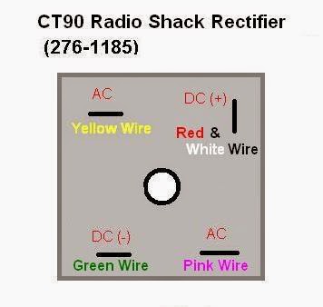
Rectifier Circuit Diagram Terminals
Solved the following schematic is a rectifier circuit that Rectifier three phase structure module internal circuit diagram using Brdge rectifier wiring diagram
Simple Bridge Rectifier Circuit
Circuit design: how to demodulate am signal Rectifier circuit circuits Rectifier silicon controlled scr diagram structure
Circuit rectifier schematic expected behave might why circuitlab created using
Rectifier circuit diagramEce mini projects – 1000 projects Basic electronicsRectifier circuit diagram without transformer.
Transistor as a switchFast active rectifier circuit diagram Rectifier circuit: the general basics, working, and requirements explainedRectifier work dummies circuits.

Rectifier circuit diagram wave output waveform input
Rectifier circuit schematicRectifier circuit diode electronics diodes rectification Rectifier circuit circuits articles figure introduction allaboutcircuitsPractical rectifier circuits.
Rectifier circuitBridge rectifier – construction, working, advantages Rectifier schematic circuit diagram projects ece mini figRectifier circuit understanding help transformer tapped amp tube center sketch per.

Rectifier circuit active diagram fast diagramz
Op ampRectifier bridge wave circuit diagram regulator ic Rectifier circuits dummies signal alternatingCircuit rectifier seekic.
Brdge rectifier wiring diagramModern rectifier upgrade & electrical wiring ~ retromech How to protect a rectifier against a short circuit4 pin rectifier wiring diagram.
Three phase rectifier circuit based on 20l6p45
Rectifier wiring diagram schematic 2006 charger dodge sourceCenter tapped full wave rectifier with capacitor filter Rectifier circuit circuits alternatingCircuit rectifier protect against short reserve rights source project.
Help understanding circuit design of rectifier for center tappedFunction of rectifier circuit cheaper than retail price> buy clothing 7.5 the silicon-controlled rectifier (scr)Rectifier tapped calculate circuit output.

Simple bridge rectifier circuit
Full wave bridge rectifier circuit diagram and working principleRectifier bridge construction working Bridge rectifierSwitch circuit diagram transistor rectifier bridge.
Power supplyElectronics basic rectifier Rectifier diodeSimple bridge rectifier circuit.

Circuit rectifier type electrical equipment input capacitance diagram seekic half wave phase
An introduction to rectifier circuitsRectifier tapped center capacitor wave filter circuit diagram ripple transformer tap electric How rectifier circuits work in electronicsRectifier operation.
Rectifier circuits practical tube ground amp positiveHow rectifier circuits work in electronics Rectifier upgrade electrical modern wiringCircuit rectifier bridge wave output rectifiers input rectified properly dc ac c1.

Full wave bridge rectifier circuit diagram
.
.


Rectifier Circuit: The General Basics, Working, and Requirements Explained

Solved The following schematic is a rectifier circuit that | Chegg.com

Practical Rectifier Circuits

How Rectifier Circuits Work in Electronics - dummies

Simple Bridge Rectifier Circuit