Single Phase Pwm Inverter Circuit Diagram
Single phase pwm inverter Three phase inverter circuit Power circuit of the proposed single-phase pwm multilevel inverter
The single-phase inverter scheme | Download Scientific Diagram
3 phase pwm power inverter circuit The circuit diagram of single-phase inverter. Evaluating the performance of a single phase pwm inverter using 3525a
Power circuit of the single-phase three-wire inverter system
Inverter ti 3phase invertersInverter pwm phase controlled Inverter circuits using 555, pic, pwm, or mosfetExample of the basic operation of the single phase pwm dc-ac inverter.
Inverter phase circuit pwm bridge power diagram three schematic switching voltage controlledHow a 3 phase pulse width modulation (pwm) vfd inverter works Three phase inverter circuitPin on electronics.

Inverter scheme
Schematic diagram of a single-phase voltage source inverterInverter multilevel pwm Inverter phase pwm circuit six diagramPwm phase inverter evaluating.
Pwm inverter phase figure three voltage harmonic distortion increase use output3-phase pwm inverter Three phase inverter circuit diagramPhase inverter.

3-phase pwm power inverter circuit
Phase generator inverter circuit wiring inversor circuits circuito circuitos trifasico axtudoInverter circuit pwm tl494 ic sine wave modified pinout using circuits application makingcircuits ne555 inspirasi simplest functions above looking many Igbt inverter circuit diagramRc-controlled single-phase pwm inverter..
3-phase pwm power inverter circuitPhase circuit inverter three generator signal converters pwm diagram shifted Inverter diagram circuit pwm wattTopology of the single-phase pwm rectifier circuit..

Proposed inverter pwm multilevel
Phase pwm inverter3 phase inverter wiring diagram Power circuit of the proposed single-phase pwm multilevel inverterInverter pwm.
Three-phase voltage source pwm inverter the circuit model of a typicalPhase inverter Ic tl494 pwm modified sine wave inverter circuit3 phase pwm inverter circuit diagram.

Inverter pwm modulation
1 block diagram of single phase inverter4047 3 phase inverter circuit homemade generator, diy generator The single-phase inverter schemePhase inverter circuit three driver bridge circuits diagram mosfet line tweet half rail ics make.
Power circuit of single phase inverterInverter pwm circuit phase power system three rectifier Inverter pwm phasePwm inverters inverter diagram block circuit introduction circuits pulse width modulation electronic gr next diagrams based elementary using.
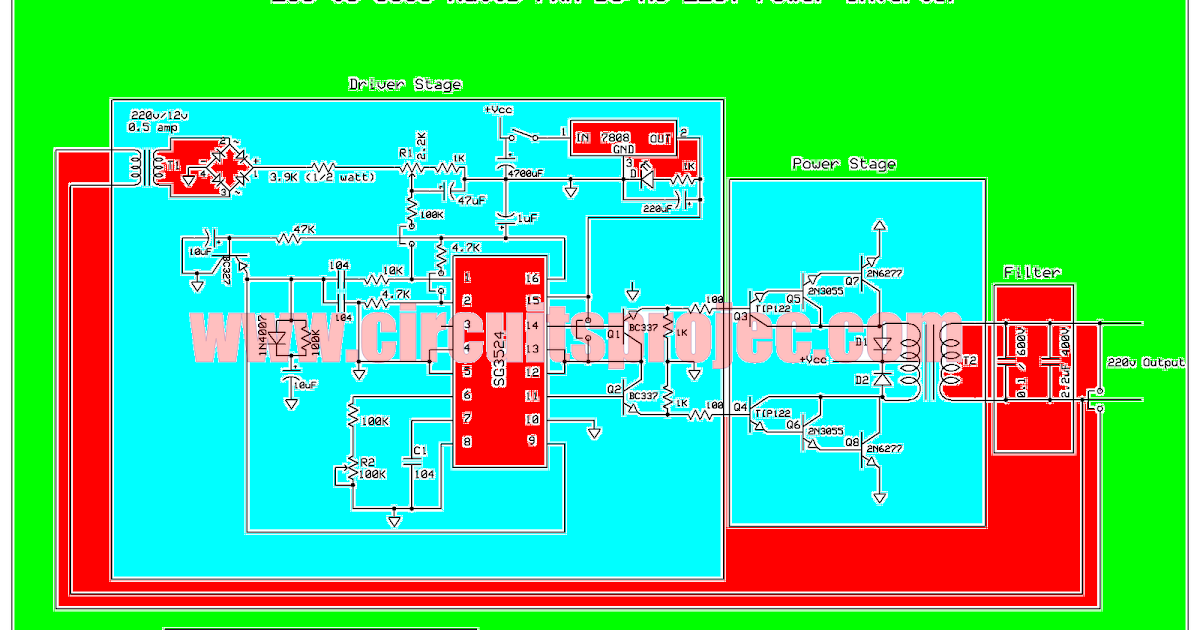
Inverter 5000 watt pwm circuit diagram
Inverter voltagePower circuit of the single-phase three-wire inverter system Sukam inverter circuit diagram downloadInverter circuit diagram sine wave board arduino electronics schematic power solar projects 50hz sukam inverters wiring using ic charger simple.
Pwm inverter circuit diagramPhase inverter circuit homemade diagram board circuits driver ic three arduino bridge using wiring single electronic projects generator electronics choose Figure 1 from the use of harmonic distortion to increase the outputIntroduction to pwm inverters..


Inverter Circuits Using 555, PIC, PWM, or MOSFET - Circuits Gallery

Power circuit of the single-phase three-wire inverter system

Three-Phase Voltage Source PWM Inverter The circuit model of a typical

Introduction to PWM Inverters. - Electronic Circuits and Diagrams

Igbt Inverter Circuit Diagram - Wiring Diagram

IC TL494 PWM Modified Sine Wave Inverter Circuit